81CJH
-
Posts
204 -
Joined
-
Last visited
Everything posted by 81CJH
-
I'll be along for a squiz around lunch time.
-
I'll be there for a look-see. Paul, the warranty's up, so I think it's about time we had that little chat. Cyas then!
-
Its great fun too. You get to curse at the games for "cheating" just like the old days. Best part is when you get jack of it you can throw the controller across the room and it don't break! Try throwing an arcade machine without breaking something :banghead:
-
...and I don't have any photos of me or others playing, so I just took a couple of my Snow Bros. high score. Remember when I said it was my favourite game? I wasn't kidding. This high score was me clocking the game on one credit.


-
Simple really... I S.U.C.K. at street fighter & mortal kombat. ...but I could easily add another three buttons, that's the beauty of it. 2 cat 5 cables, each with 8 wires. A joystick takes 4 wires, one wire per button after that and one for an earth, so I could expand up to another 4 buttons on the Player 1 table & 6 on player 2. Out of interest, it cost me around $150 to build both tables ($69 just for the kb encoder), and I already had the PC kicking around gathering dust.
-
From the local ROM-Grocer, of course. My absolute all time favourite is Snow Bros, which you can get from here.. Enjoy!
-
All righty then. Who remembers going to the arcade halls back when the machines only cost 20c a go? Double Dragon, Street Fighter, Golden Axe, Snow Bros.... all the classics. Well I've been messing around with MAME in recent months, and have built a setup which is portable, durable and pretty much fool proof. As it turns out you can still buy brand new parts for arcade machines, and they're not even that expensive! A local computer store in Brisbane Gamedude sells joysticks and buttons and all that stuff, as well as keyboard encoders to hook it up to a PC, which is really cool. So, rather than build an arcade cabinet which is large and not very portable, I bought a bunch of buttons & a couple of joysticks, and mounted them into a pair of stable tables! I also added a couple of extra buttons mounted in the Player 1 table which allows for game swapping & shutting the PC down. Each stable table has two cat5 network cables which run back to the keyboard encoder mounted in a dedicated MAME PC, which just runs a minimal install of Windows 98. The PC is pretty old and crap (you don't need much to run MAME), but has a basic 3d card in it with a tv out, and I've made a short 3.5mm to female RCA lead, so that all you need is an off-the-shelf RCA cable to run both video & audio into the AV input of any TV. If you wanted to get hardcore portable you could possibly adapt this to suit a laptop or one of those barebones mini PC's. Take a look, fire off any questions, and go build yourself one just like it! It's awesome fun.


-
I missed out Wed night, anyone heading out tomorrow night?
-
Common sense has nothing to do with it, It's about personal preference, we already established that. ... except having mudflaps does make sense.
-
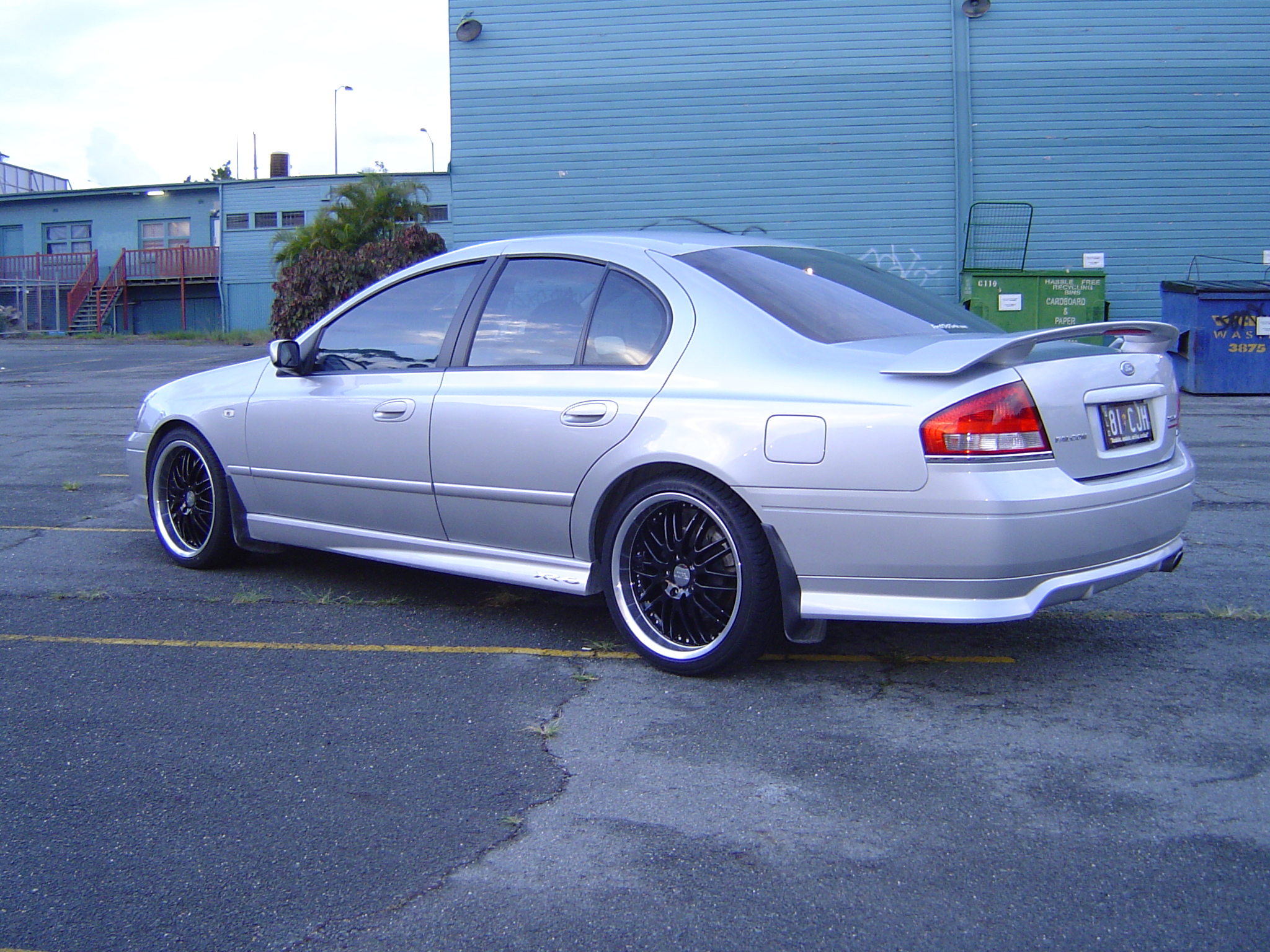
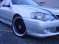
Got the wheels on today... Ruff Racing r281 (Black centre, polished lip) 19"x8.5" all 'round. If I had the option, I would have liked 18's, with 7.5" up front and 8.5" on the back. Regardless, I'm happy with the result. I certainly agree that it would look better lowered a couple of inches, but having owned lowered cars in the past, I've grown weary of sacrificing practicality for the sake of looks alone.

-
Getting some 19"ers on mine tomorrow... Stock springs. I was wondering how it would look, but having seen the pics you guys put up I'll be happy with stock height. I mean I'm pretty happy with stock height on 17's, so I don't see how bigger rims is gonna make it look crap.
-

How-to: Dimming Aftermarket Gauges With Dash Lights
81CJH replied to 81CJH's topic in Electrics Workshop
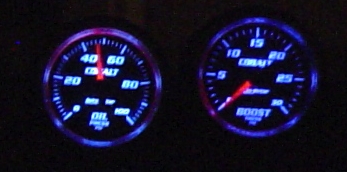
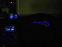
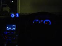
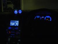
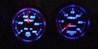
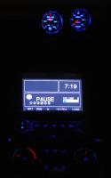
Sorry about the crap photography, I need a tripod or a better camera... or both. So, there's one of each dimmer setting, and a couple more on max brightness trying to get a good shot of the gauges.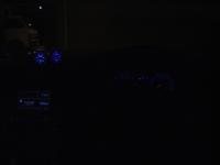
-
How-to: Dimming Aftermarket Gauges With Dash Lights
81CJH replied to 81CJH's topic in Electrics Workshop
Nice work mate, glad I could help. -
How-to: Dimming Aftermarket Gauges With Dash Lights
81CJH replied to 81CJH's topic in Electrics Workshop
Well ideally, grab a 1k ohm pot & hook it up so you can dim the gauges manually. If possible do it in a darkened garage so you can compare the brightness of the gauges to the rest of the dash. I found that on my gauges that at the highest brightness I wanted I was only feeding about 5.3V into the illumination wire. Once you have the gauges at the maximum brightness you require, you can turn off the lights, disconnect the pot without moving the knob and measure the resistance across the two legs you had connected. The value you get is the resistance you should use on the collector. Nice & simple, no maths. *Note: The collector resistor determines the maximum brightness of the gauges, while the emitter resistor determines minimum brightness. If you don't have a 1k ohm pot, just stick +12V into the gauges through a multimeter (in series) to measure the DC current being drawn. That will give you the maximum current required by the gauges and you can work out your resistor values from there. Example: If your gauges require 50mA (0.050 Amps), then 12V / 0.050A = 240 ohms. Once again, this is the collector resistor. Also bear in mind that if you need more power you need to drive your gauges, you may need 1 Watt resistors, not 1/2 Watt. Power = Current x Voltage. Remember to use the voltage drop across the resistor to calculate the power, not the full 12V. As for the emitter resistor, I'd have a guess at keeping it around 1/3 of your collector resistor value. I had a 300 ohm collector resistor & a 110 ohm emitter resistor, and the ratio seems about right. Remember, all we're doing here is supplying for more current to feed the extra gauge. The proportions should remain the same. Good luck! -
How-to: Dimming Aftermarket Gauges With Dash Lights
81CJH replied to 81CJH's topic in Electrics Workshop
Goddammit. Hey while you're in there can you tell me where all your gauge wires are hooked up? Maybe that's why mine is screwy. -
How-to: Dimming Aftermarket Gauges With Dash Lights
81CJH replied to 81CJH's topic in Electrics Workshop
Which wire? (Colour etc) Do your gauges dim properly, or are the brightness changes only slight? -
How-to: Dimming Aftermarket Gauges With Dash Lights
81CJH replied to 81CJH's topic in Electrics Workshop
You'll probably have to adjust the values a bit. Best bet is to use a multimeter to measure the current drawn by the gauges, then use ohm's law to calculate the value of the resistors. Bear in mind you may need to switch up to 1 Watt resistors depending on the extra current required. -
Just threw up a new topic with all the nuts, bolts & juicy bits.
-
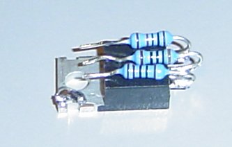
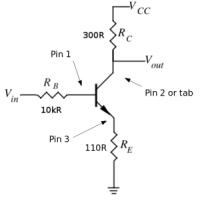
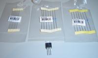
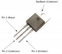
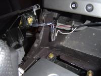
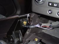
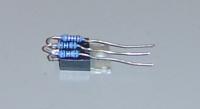
This is a How-To guide for getting your aftermarket gauges to dim automatically, in sequence with your dash lights. The circuit described below may also be useful if you have an aftermarket head unit or LCD screen(s) installed that supports display dimming, rather than just day or night mode. Background: Previously, the way most people dimmed their gauges was by using a 1k ohm potentiometer (or pot, aka rheostat) connected to the +12V illumination wire from the cigarette lighter or traction control switch. If you connect the Blue with White stripe wire from the cig. bulb to the left pin, and gauge illumination wire to the middle pin, you can adjust the brightness of your gauges just by turning the dial. The down side to this is that you need to put the potentiometer somewhere accessible, yet out of the way, so that you can adjust the gauge brightness when required. How it should be: Ideally, your shiny new gauges should be the same brightness as your dash, and dim along with all your other dash lights using the same button. GOOD NEWS! This is exactly what my new transistor circuit does. Better yet, it's dead simple to build, costs less than $2.50 and can be installed in roughly 30 minutes. Parts list (Jaycar): NPN Transistor: ZT2285 - $1.20 (TIP31) Base resistor (RB): 10k ohm RR0596 - $0.38 (1% 1/2 Watt, Pack of Collector resistor (RC): 300 ohm RR0559 - $0.38 (1% 1/2 Watt, Pack of Emitter resistor (RE): 110 ohm RR0549 - $0.38 (1% 1/2 Watt, Pack of *Note: Collector & Emitter resistor values are correct for use with a pair of Autometer Cobalt series gauges. Different brands of gauges or dimming more than two gauges will require different values. The 10k ohm Base resistor should be universally correct. Pin out for transistor (writing side up): Pin 1 (Left) = Base Pin 2 (Middle) = Collector Pin 3 (Right) = Emitter Pin 4 (tab/casing) also = Collector. Construction Notes: Over stating the obvious here; Soldering irons get hot. They melt solder pretty well, so don't be surprised if your finger gets melted if you touch the hot bit. Surprisingly, the wires & components that you're soldering also get hot - while you're still holding them. See where I'm going with this? Good, let's get on with it... Shorten the legs on the transistor & on one end of the resistors, leaving enough length to be able to bend the resistors up and over the transistor (see photo). Solder the short ends of the resistors onto the transistor legs, double checking that the correct value resistor is attached to each leg (See circuit diagram, & use a multimeter if necessary). This part is best done on the bench with a small hobby vice or a pair of pliers to aid alignment. You can do it in the car, but resistors are quite small and like to fall in hard to reach places when you drop them because "OWW, I just burnt my finger". This is what your circuit should look like. Leave bending the resistors up & over 'till later. I ended up bending them back straight anyway to make the in-car soldering easier. Note: If possible, use 2 to 3cm lengths of heat shrink to insulate your soldered connections. This is the best way to prevent short circuits from wires or component leads touching each other. Electrical tape will suffice if you don't have heat shrink, but is quite fiddly. Solder an extension wire (about 10cm long) to the thick black earth wire from the cigarette lighter socket. Solder the extension to the 110 ohm resistor connected to pin 3 of the transistor like in the circuit diagram. Now, cut the two wires to the cigarette lighter bulb holder and strip the ends, leaving a little wire on the socket for reconnection at a later date (or just bin it). Solder the Blue with Red stripe wire to the 10k ohm resistor connected to Pin 1 of the transistor. Solder the Blue with White stripe wire to the 300 ohm resistor connected to Pin 2 of the transistor. Solder the illumination wire for the gauges straight onto the top tag of the transistor. With all your wires soldered on & heat shrink applied & shrunk, bend the resistors up and over the front of the transistor so they lie flat on the top of the transistor. Use electrical tape and wrap around the package (to insulate the metal tab & rear casing), then tape the package to the wiring loom for the cigarette lighter. This makes for a nice neat package that is fairly solid and well protected. It's as easy as that! :roll: Some more info for those interested: Unfortunately there doesn't seem to be a wire that you can just hook your gauges up to & have them dim properly right out of the box. This is because of the way Ford dim their dash lights. The dash lights are not dimmed by a variable positive voltage, as you would expect. Let's look at the cigarette lighter illumination bulb, since it's just an ordinary light bulb and is simple to imagine. When the park/head lights are on a constant +12V is applied to one side of the bulb, regardless of the dimmer setting. The brightness is actually controlled by raising the potential of the "earth" wire using Pulse Width Modulation. When the dash lights are at their dimmest (1st setting), you have your +12V on one side of the bulb, but the "Earth" wire is actually reading +8.45V, with respect to earth. This means there is only 3.55V across the bulb, which makes it dim. As you increase the brightness setting of the dash lights, the voltage of the "Earth" wire progressively drops, getting closer to earth potential and increasing the voltage across the bulb. When the dash lights are brightest (4th setting), the "Earth" wire reads +0.265V, creating almost a full +12V across the bulb, which = bright. Pulse Width Modulated ground wire voltages: Dash lights dimmest (1): 8.45V (2): 5.70V (3): 3.01V Dash lights brightest (4): 0.26V Our aftermarket gauges are expecting to be fed with a variable positive voltage, and don't allow for this method of dimming. We're given one wire for voltage input, and the other side of the gauge bulbs (or leds) is grounded inside the gauge. So you can see that neither the +12V wire or the PWM'ed earth wire is any good to us by itself for the purpose of dimming our aftermarket gauges. If you were to hook up the +12V wire from your cigarette lighter bulb to the gauge illumination input, it wouldn't dim at all. If you hooked up the "Earth" wire, the gauges would dim, but they'd get dimmer as the dash lights got brighter. What I've done, is use the PWM'ed earth wire to drive an inverting transistor circuit, which gets the dimming happening "Right Way Up". When the dash lights are dimmest (PWM = 8.45V), the transistor is turned fully on and draws the supply voltage down closer to earth, making the gauges dim. As the dash lights get brighter, the PWM signal gets less and less, turning the transistor further off, allowing the output voltage to rise closer to the suppply voltage. When the dash lights are brightest, the transistor is fully off and you're essentially feeding the gauges directly through the 300 ohm Rc resistor. Well I think that's more than covered it. If you have any questions or comments, feel free to reply here or PM me. Enjoy.

-
P.S. I now have the circuit installed in the car.
-
No pot, it dims like it should, cycling through like all the rest of the dash & ICC. My gauges are now pretty well spot on matched for brightness with the rest of the dash, but like I said, different gauges may be brighter/dimmer than mine.
-
...sorry folks, ran out of edits on the last post. Here's a new circuit diagram showing a 110 ohm resistor (not 100 ohm)dimmer_circuit.bmp
-
Well guys I'm happy to report that my circuit works a treat. All up it costs $2.45 and can be built and installed in 30min, if you're handy with a soldering iron and have pulled your dash apart a few times. I'm yet to take photo's or exact voltage measurements, but here's the parts list and circuit diagram for those who want to give it a shot: dimmer_circuit.bmp Parts: 1x 10k ohm resistor (Jaycar Part# RR0596 - $0.38) 1x 110 ohm resistor (Jaycar Part# RR0549 - $0.38) <---- edited: previsouly had 100 ohm (sorry) 1x 300 ohm resistor (Jaycar Part# RR0559 - $0.38) 1x NPN transistor (Jaycar Part# ZT2285 - $1.20) The resistors are 1% tolerance metal film resistors, and are probably a bit special for the job, but at $0.38 for a pack of 8, I figured it wasn't worth looking for cheaper ones. The transistor is also overkill given the application, but I chose it because of its size and robust nature. Once again, for a buck twenty, I'm not too fussy. Output pins on the transistor (text side up): left = Pin 1 (base), middle & tab casing = Pin2 (Collector), right = Pin 3 (Emitter). Also see attached image. TIP31_Pinout.bmp Connections: Negative wire from cig. bulb to Pin 1 (through 10k resistor) Positive wire from cig. bulb to Pin 2 (through 300 ohm resistor) Black Ground wire from cig. lighter socket to Pin 3 (through 100 ohm resistor) Gauge illumination wire to Pin 2 or tab/case (no resistor) I haven't actually put mine together properly or installed it yet, I just tried it out on some breadboard to make sure it would work. I'll try to do a nice neat job of putting it together & take photos 'n' stuff to make a dinky dye how-to if the moderators would like one. Please also note that the above circuit is good for a pair of Autometer Cobalt series gauges. Different gauges will require different amounts of power, so you will need different resistor values attached to pins 2 & 3 to get brightness right for your gauges. Enjoy.
-
Sorry, missed your post earlier. In short, I don't know why mine should be different to anybody else's gauges. The fact is that when my gauges were installed they did not dim with the dash lights, and did the weird night light thing on unlocking. Upon investigating further, this is what I found. The circuit I'm building is also intended to bring the gauges down to the same brightness of the rest of the dash. I haven't built it yet, but I picked up the parts from Jaycar just now for under $3. ...But you still have to pull out the TC button and adjust the trimpot to dim the gauges, right? I'm hoping to get them to dim automatically with the rest of the dash lights like they should. Hopefully should have an answer for y'all by tomorrow morning. ...Basketballer Vince: I don't know what seventytwo's pot is, but a 1k ohm potentiometer should do the trick. Jaycar part # RP7504 - $1.75.