
Ninka
-
Posts
1,850 -
Joined
-
Last visited
-
Days Won
1
Content Type
Profiles
Forums
Gallery
Events
Store
Articles
Media Demo
Everything posted by Ninka
-
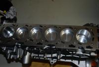
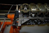
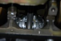
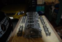
Not sure on the poost Luke, all depends........ Oil pump was modified, with billet gears, and re-working of oil relief passages, to allow the pump to bleed oil more quickly on overpressure, preventing pressure spikes on high rpm, and with that, hopefully avoiding valve lift, and other unintentional consequences. Oil pump was then ready to be fitted. Well next step was the fitting up of the block, pistons and crank. There I first started by carefully measuring each bore, and recording the size against the tiny differences between each of the pistons, so I got an optimised, and as near to 100% equal tolerance across all 6 cylinders, which I was very happy to have achieved, as near as I think possible. Piston ring gaps were then made to the tolerances I have used on my current engine, and again taking great care that they were all equal. Crankshaft was then checked, and oil passages radiused to clear the nasty sharp edges which are there from factory, after which everything was cleaned carefully, and assembly could begin. First the crankshaft was fitted and checked for thrust clearance, then the 6 pistons were pushed into the cylinders, and small end bearings fitted, paying particular attention to the custom drilled oil passage in one of the shells (as supplied by Atomic) to allow the pressurised oil feed to the gudgeon through the centre of the conrod. This was followed by careful torquing of the ARP bolts on the small end bearing caps, ensuring proper lubrication using moly grease supplied with the bolts. After finishing all the little ends, the main cap bolts have to be removed again, to allow the heavier Atomic girdle to be fitted (cannot be done earlier, as bolts for con rods would then be inaccessible, and unable to be torqued) girdle was then fitted, and main cap bolts greased, and torqued to specified torque. Oil pump was then fitted. After this it was just a matter of bolting it all together, and fitting the hardened cam drive gear on the crank, heavy duty cam chain and tensioner, and then throwing on all the covers and sump, which all went pretty well without incident. Prior to fitting, I 'prettied up' the front cover, with a high gloss silver aluminium paint, and re-painted the valve cover in the nice 'T' RED. A few more photos on the assembly of block/pistons attached.
-
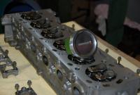
Oh, I forgot, I also fitted Atomic Titanium valve spring retainers, just to keep the weight of moving parts down a bit Can be seen in pic DSC_1620. Also finally got my picture library cleaned out, so a few pics attached.
-
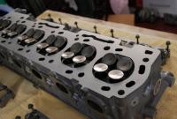
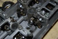
Thanks Guys :sungum: The process started by stripping back a good BA N/A head I had from an engine I bought some years ago, I then had gasket surface and seats machined, and all valves vacuum checked with the new single groove exhaust valves. The bare N/A head is identical to the Turbo heads, except that the exhaust valves are different (higher heat tolerance), so these needed to be replaced. I looked at the option of replacing with Ford standard Turbo valves, but ended up choosing a proprietary swirl polished single groove valve, as the single groove design 'clamps' the valve stem, stopping the valve rotating quite as much as the looser multi-groove units used stock. This helps a little with noise, but importantly, at higher revs, reduces valve wear, as the exhaust valve is moving more or less straight up and down, with virtually no rotation when it meets the seat. Following the preparation, I checked the valve guides and other components, fitted new valve stem seals, Atomic valve springs, hydraulic lifters and rocker arms - Head done.....
-
You need to remove the valve cover, turn the engine until the 2 dots on the Cam Phaser sprockets are visible, mark Cam Chain for both sprockets (it is critically important that Phasers are fitted back in EXACTLY the same spot), retract and secure the cam chain tensioner, then remove one of the Cam Phasers and both Cam Shafts, after which you can remove the rocker arms and get to the lifters, fitting is reverse of listed procedure. Special tools needed are: Chain Tensioner retractor tool (although you can use a piece of bent wire) TORX socket for Cam Phaser, and Torque Wrench for re-tightening the Camshaft bridges (10Nm) Extreme care has to be taken when unbolting the Camshafts, as they have to be undone very evenly to ensure you don't break the bridges holding the Cams in place, or bend the Camshafts, same applies for fitting them back after replacing the lifters. Hope this helps
-
Well it's been a while since I posted anything substantial, so for those of you who know me, and have followed my past technical adventures, you will know I'm a bit of a nutter for mechanical finesse, and in the quest for a VERY strong engine, with a stock level of mechanical 'noise' I.e. no rattely noises at all, I am just in the process of completing my latest engine project for my '02 BA XR6T (the one with the ZF 6 speed). I thought I would share what I have been doing, for those of you interested in the technical aspects of the engine building process. New engine is built with the following modifications over stock BA: Head machined and vacuum checked BF Cams Titanium Valve Spring Retainers Harder Valve Springs Stainless single groove race Exhaust Valves Heavy Duty Cam Chain Hardened Cam Chain Gears Heavy Duty Chain Tensioner Modified Oil Pump with Billet Gears and larger passages Engine Block checked for wall thickness and tunnel straightness, machined and bored to proprietary tolerances Crank checked and oil passages radiused Cosworth Forged Pistons Heavy Duty Billet Con Rods (998kw rated) Race Bearings Heavy Main Bearing Brace Crome Moly Heavy Duty Flexplate and ARP bolts I am building engine myself, but all performance parts have been supplied by Atomic, so thanks to Brad for his help with getting this together. I hope to get the time over the next few weeks to change the engine over with my current unit, which last we dynoed it, ran 363 rwkw, and hasn't missed a beat, but the Mahle pistons are not 100% quiet at the tolerances I used for that engine, so here's hoping the next one does the trick......
-
Crank and blocks are the essentially same across all BA/BF cars, FG is a little different, as dipstick hole is located differently. Heads are different between N/A and Turbo cars, as Exhaust Valves are different alloy (BA/BF essentially the same), and FG heads have a different 'swirl' inlet design. Hope this helps
-
Steve, Please PM me the route. I have other appointment @ 4pm, but depending on planned route, I may join in th fun......
-
I read 2 PM somewhere, so assume this is right???
-
If the weather is not too bad, I'll pop out for a ride, so we'll see who shows up... Hmm RWD, lot's of torque and wet roads
-
Ditto for me.....
-
Sure Luke, Just come to my place a couple of hours in advance, and you can wash and polish the yellow lady before the cruise
-
So which date is this? June 3rd??? If so, I will probably come for a spin, barring pouring rain (she would get a shock, living 100% in a warm dry garage these days )
-
"Hand Raised"
-
OK Guys, most of you probably don't know or remember me, as it's been a while since I was really active here, but I think it's time to drag the semi-retired yellow lady out of the garage for a spin, so I'm in for the 20th.. Luke please PM me the details once you have it all laid out. See you all on the day. Cheers, Ninka (Allan)
-
Sounds like a good long cruise to get the 'old' girl out for a nice run, and I agree with your view of rules as well Mat, so no problem there!
-
This is quite fiddely to do, and you must know what you are doing, otherwise it will come out worse than before, and may whine as a bi*ch. Whole rear subframe has to be removed to get to the diff, so quite a few hours involved before even touching the diff. Shop around, but make sure they know what they are doing!!
-
Sorry guys, something's come up, so I have to drop out this time around
-
Ahh, interesting. Block was near brand new, only ran in my car for a few thousand k's before I broke a ring land on one of the stock pistons it came with as a short motor from FoMoCo. Cylinder walls were tested before engine build, so must just have reached the limit for this particular block, maybe an imperfection in the cast, who knows!! Glad to hear things held up otherwise, as I would have been puzzled if pistons or rods had broken.
-
Yep, agree - BIG job, and expensive too! The territory box wil fit physially, BUT not electronically, so that's where the biggest headache lies. Search my threads from a couple of years ago, you will see what was involved. the 6 speed has worked floorlessly since, so one of the best mods to my car
-
Interesting, piston slappage, you sure about that? I built the engine, and I can guarantee you that it did not have excessive piston slappage Maybe the fact that the tune in the car was very aggressive could have something to do with the engine breaking! Feeding 24psi into it @ 3000rpm will destroy engines, no matter how well they are put together, but Russ wanted that 'tyresmoking rush' from low rpm, so that's the result. What happened is most likely a high throttle input from low rpm, a piston skirt either bent or broke due to excessive boost, causing the damage to the block, rods were 600 kw rated Atomic rods, so I don't see them breaking easily. The Mahle pistons in this particular engine, are running well in my own car right now, and though not 100% rattle free, they are very quiet, with only slight piston noise evident at idle, and I'm running 364rwkw with an auto, and never had a problem. Hope this sets the record straight - YOU PLAY, YOU PAY I regret this was the result for the new owner, and I hope the car is back on the road again soon
-
Haven't been on the forum for a while, so Hiddeous made me aware of the cruise, and I thought I would come along for a ride Name added to list in 1st post in yellow
-
Looks suspiciously like my various con rods, as photographed by Hiddeous
-
I agree, except you only have H4 (main light) and H7 (auxillary light) in you headlights. not any H3.
-
You have got Halogen H4 hi/lo in you main headlights I.e. they perform both the lo and hi function, but on hi they are supplemented by the inner auxillary hi lamps as well. Globes for main lamps are H4 and must be bi-Xenon if you plan to replace these (be real careful to get globes that actually fit the lamp socket, as some of the cheap Chinese ones are assembled with small screws which get in the way) Auxillary lamps are H7 Hope this helps
-
Can be done, look for my thread "BA to be BF'ed" where I describe the process. The ZF is a great box, and it physically fits the BA no problem, it is the electronic interface which will cause you the greatest amount of work. Our cars,(BA and BF) use a CAN Bus communication network, and several modules are linked in this network (BEM, PCM, RCM, Cluster and the TCM in the ZF) and it is not possible to upgrade one of these to BF version (TCM) as the other modules will not recognise the upgraded unit, and refuse to communicate. I have upgraded my car to complete BF F6 specification, including changing most of the wiring looms and mentioned modules, ignition lock etc. Cost will depend what you can find a complete upgrade from a donor car for, but you will have by far the least trouble by lifting everything from a BF to you BA. Once done it works a charm, and I am running 363rwkw through my ZF (FPV F6 unit) with no trouble at all. Send me a PM if you have specific questions about this.